Computational Fluid Dynamics (CFD) is a computer-based tool for simulating fluid movement. The main advantages of CFD over other fluid mechanics studies include: substantial savings in time and cost, the analysis of systems or conditions that are very difficult to simulate experimentally (as is the case of the airways), and a practically unlimited level of detail. We used the Ansys-Fluent CFD program to develop a conducting airway model to simulate different inspiratory flow rates and the deposition of inhaled particles of varying diameters, obtaining results consistent with those reported in the literature using other procedures. We hope this approach will enable clinicians to further individualize the treatment of different respiratory diseases.
La dinámica de fluidos computacional (CFD) se define como la técnica informática que busca la simulación del movimiento de los fluidos. Las principales ventajas de la técnica de CFD sobre otro tipo de estudios de mecánica de fluidos son la reducción sustancial de tiempo y costes en los experimentos, la posibilidad de analizar sistemas o condiciones muy difíciles de simular experimentalmente, como es el caso de las vías aéreas, y un nivel de detalle prácticamente ilimitado. Utilizamos el programa de CFD Ansys-Fluent para elaborar un modelo de la vía aérea de conducción que permite la simulación de distintos caudales de flujo inspiratorio, así como del depósito de partículas inhaladas de diferentes diámetros, obteniendo resultados concordantes con la literatura existente utilizando otros procedimientos. De este modo se pretende abrir una nueva vía a la individualización de los tratamientos para las distintas patologías respiratorias.
Computational Fluid Dynamics (CFD) techniques are of great interest in current pulmonology research. In 2012, the Food and Drug Administration (FDA) announced a new research project entitled “Predictive Lung Deposition Models for the Safety and Efficacy of Orally Inhaled Drug Products”. The goal of this proposal was to develop a CFD model of orally inhaled medication that could predict drug deposition characteristics and physiological parameters in the lungs. Judging by the latest worldwide CFD conferences, the use of these techniques in medicine has been expanding. For example, in the “Bio-engineering” congress of 2003, only 1 communication was presented, specifically on the study of blood circulation, while in 2007, 7 communications on circulation and 5 on breathing were published.
CFD is as computer-based tool for simulating the movement of fluids. It is a branch of fluid mechanics that uses numerical methods and algorithms for analyzing and resolving problems related with fluid flow. It is based on a wide range of sciences, such as mathematics, computer sciences, engineering and physics, all brought together in the construction of systems for modeling fluids.1 CFD has progressed thanks to the increasing power and lower cost of computers, and it is now used for the resolution of the Navier–Stokes equations. These equations governing the movement of fluids were discovered simultaneously by French engineer, Claude Navier, and Irish engineer, George Stokes, over 150 years ago. They are derived from Newton's laws of movement and apply to any flow. They can be used to determine the velocity and pressure, and thus the behavior, of a fluid in any point in space. Particularization to specific cases is defined by the so-called boundary conditions and by the initial values entered. Because of their complexity, only very basic Navier–Stokes equations can be solved analytically, and advanced software designed for processing these data is essential.
The advantages of CFD analysis can be summarized as follows: substantial savings in time and costs offered by the new designs, the analysis of systems or conditions that are very difficult to simulate experimentally, and a practically unlimited level of detail.
Take, for example, airflow in the lungs. Along with the equations, the initial and boundary conditions set for the variables and the solid surface need to be entered in the CFD program. Conditions set for variables are defined by air velocity and pressure, and the solid surface conditions are defined by the shape of the airways, expressed mathematically in coordinates. Before solving the Navier–Stokes equations for the airway as a whole, the program must first resolve them in a finite number of points in space. To achieve this, the lung must first be represented as a mesh: the greater the number of points on the mesh, the more precise and real the simulation will be, but the more difficult it will be to generate and resolve. In cases with complex geometry, this phase can take days or even weeks.
Generating a Geometrical Model of the AirwayTo generate a 3-dimensional model of the airway, the design proposed by Kitaoka et al.,2 complemented by the model described by Weibel3 was selected. Wiebel's conventional model3 describes airway bifurcation modes. It designates the trachea as the first airway (order 0), and assumes that each airway gives rise to 2 branches (regular dichotomy). Thus, the main left and right bronchi are order 1, and there are at least 23 bronchial generations up to the alveolar ducts. Thus, there would be 223 (8388608) order 23 airways, which, as can be imagined, would be practically impossible to simulate with CFD techniques without some form of simplification. The diameter of each branch narrows according to the formula dz=d0·2−z/3, where z is the order of the airway generation and d its diameter. This ratio is maintained until generation 16 (conducting airways). After generation 17, there are few changes in the dimensions of the respiratory tract, since the airways are now more or less alveolized (transitional airway and respiratory zone).
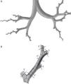
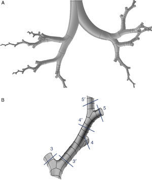
Weibel's model3 did not take into account the spatial arrangement of the branches, and must be supplemented with the findings of more recent studies to generate a 3-dimensional model of the airways. Kitaoka et al.2 managed to design a realistic 3-dimensional model of the lung on the basis of 9 fundamental rules that indicated bifurcation angles and planes between branches, the relationship between the diameter of a parent branch and its daughter branches, the length of the branches, etc. On the basis of these rules, the geometric model of the bronchial tree up to airway generation 16 was produced using the Gambit program, part of the Ansys-Fluent CDF simulation package.4 The complete model up to the end of the conducting airway would comprise a total of 65536 terminal bronchioles. Since this would need exceedingly long calculation times for solving the Navier–Stokes equations, it had to be simplified. To this end, the program was improved by adding a User Defined Function (UDF). This UDF consists of a new code especially designed for the airway that is used to generate an overall simulation of the behavior of the air in the 65536 branches of the complete model, working with only 8 bifurcations. To achieve this, the boundary conditions of the developed branches must be imposed on their truncated homologs. Thus, the behavior of the air in the developed branch is applied to the truncated homolog. The model developed in only 8 bifurcations is shown in Fig. 1. This partially developed model has been studied by several working groups,5–8 and has been shown to be effective for simulating the entire airway, while saving on computational costs.
(A) Three-dimensional model of conducting airway (up to generation 16), developed in only 8 bifurcations, aimed at reflecting the anatomical distribution of the lung lobes. (B) Details of one of the developed bifurcations. The User Defined Function applies the characteristics of the air in each of the portions of the developed airway to its truncated bifurcation homologs; i.e., what happens to the air in 3′ is applied to the truncated homolog 3; what happens in 4′ is applied to the truncated homolog 4, etc.
The upper airway (nose, mouth and pharyngolarynx) was also added to the model to complete the whole conducting airway. The nose (Fig. 2A) is a simplification of the model used by Castro-Ruiz.9 This model was developed from coronal slices obtained by computed tomography (CT), and the outlines were used in the reconstruction of the longitudinal surfaces. The mouth (Fig. 2B) and the pharyngolaryngeal regions (Fig. 2C) are a reproduction of the model published by Stapleton et al.10
(A) Geometry of the nose, based on the model developed by Castro-Ruiz.9 On the left, coronal slices at certain levels of the nasal apertures, obtained by CT, with their corresponding location in the model (right). The longitudinal surfaces of the model could be reconstructed using the perimeter of the coronal slices. (B) Geometry of the mouth. Various coronal slices are shown (left) with their corresponding location in the model (right). (C) Geometry of the pharyngolaryngeal region. Various slices are shown in the model (left), with their location in the image on the right.
The same process used for the nose was applied to the construction of the mouth. The geometry of the pharyngolaryngeal region is more complex, since its 3 entry orifices (2 posterior nasal apertures and the oropharyngeal isthmus) have to come together in a single duct (the pharyngolaryngeal region), opening into the trachea. The complete conducting airway model, from the nose to the generation 16 bronchioles, is shown in Fig. 3.
Preparation of the Numerical ModelMeshingThis is a basic part of the process, since it determines the correct solution of the Navier–Stokes equations. The mesh is based on the geometrical model described above, and is divided into as many regular cells possible. Given the morphology of the airways, the geometric form best suited for generating the mesh is the tetrahedron. These tetrahedrons must be the same size as the ducts, and their shape must meet certain requirements to make them suitable for the equations; if the tetrahedrons are exceedingly misshaped or if there are large differences in size between the neighboring regions, the results may be incorrect. The Gambit program from the Ansys-Fluent CFD package can also be used to create the mesh.4 This process produces approximately 1 million cells. Other meshing procedures with larger or smaller number of cells were tested, but 1 million was found to be the best number for this airway model, providing cost savings while not compromising the quality of the data. Several details of the meshing model are shown in Fig. 4A and B.
Boundary ConditionsSolution of the Navier–Stokes equations for each problem depends on the initial and boundary conditions set for the variables (in this case, air velocity and pressure) and the solid surface (the geometrical airway model). The air entry surface (the nasal apertures or the mouth) and the exit surfaces (the terminal bronchioles) must be entered into the Fluent program of the Ansys-Fluent CFD package.4 The entry boundary conditions will be the respiratory flow rates to be simulated (flow rates of 15, 30 and 75l/min were used) and the exit boundary condition is set at a relative pressure of 0. The pressure value is unimportant, since the result obtained will be the differences in pressure; during inhalation, pressure will be negative and during exhalation, it will be positive, to allow the entry and exit of air in the model. The type of fluid under study must also be entered into the program: in this case, it is air.
Equation SolutionWhen the working boundary conditions have been specified, the program is now ready to solve the Navier–Stokes equations for each of the cells of the model. By solving all the equations for each of the cells, the program determines the overall behavior of air in the airway model. Equations are resolved using an iterative method, starting with an approximate solution and using each iteration to approach the real solution. The process is complete when the results between one iteration the next differs by less than 10−5, and convergence has been achieved. A certain number of iterations are established in the program. If the termination criteria are met, the simulation terminates, and if not, the program calculates them all. If convergence is not achieved at the end of this process, more iterations are programmed.
Simulation of Particle Deposition in the ModelOnce the flow within the lung has been simulated, the trajectory of particles introduced into the model, depending on their velocity, size and weight, can be calculated. The characteristics of the particles under study are introduced into the program as follows:
- •
Inert material: density 1000kg/m3.
- •
Size: particles 1, 5, 10, 15 and 20μm in diameter.
- •
Velocity: same velocity as air, since they are transported by air.
- •
Seeding density: 0.5%.
- •
Number of particles injected in the model: 98.658.
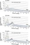
The option indicating that each particle that comes into contact with the wall becomes trapped there is activated. Particles may be introduced via the nasal apertures or by the mouth. Since inhaled medications are administered by mouth, the second option is selected. The Fluent program calculates the trajectory of the particles, establishing the deposition fraction (DF) in each of the model's generations. DF is defined as the ratio between the mass of particles trapped in a certain area of the model and the mass of all particles introduced into the model. FD for the airflows and size of the study particles is shown in Fig. 5. It can been seen that, as the size of the particles and flow rate increases, particles tend to become trapped in the early generations of the airways, particularly between the oropharynx and generation 5.
Deposited fraction in the airway model (DF) for particles 1, 5, 10, 15 and 20μm in diameter, using inhalation flows of 15, 30 and 75l/min. Note how, as the inhalation flow increases, the particles tend to become trapped in the oropharyngeal region (OP) and in the first bronchial generations.
These results were compared with those obtained by Conway et al.,11 as shown in Fig. 6 (oropharynx excluded). Conway used scintigraphy and SPECT imaging techniques to measure aerosol deposition in the respiratory tract of healthy volunteers. Conditions used were an inhalation flow rate of 18l/min with an aerosol particle diameter of 5.76μm. These results were compared with those obtained by CFD simulation using a flow of 15l/min and 5μm particles, up to generation 16 of the airway. The underlying trend in both studies is an increase in pulmonary deposition as the generation increases. Differences between the studies may be related to the boundary conditions and/or the numerical model used, but the result can be seen to show the same trend.
Comparison between deposited fraction, using an inhalation flow of 15l/min and particles of 5μm, obtained in the experimental study by Conway et al.,11 and CFD simulations obtained in this study.
One of the most notable aspects of CFD is its multidisciplinary nature. CFD as a technique has been in development for years, but applications have nearly always been focused on the aerospace industry or the design of new automobile prototypes. Gradually, however, in recent years, it has begun to be used in medicine, but nearly always in blood circulation dynamics. Its use in the study of lung diseases and the pulmonary deposition of inhaled particles is an innovatory approach. Very few groups have studied the right way to simulate the flow kinetics of materials within the lungs; to date, designs have generally used simplifications that make the model incomparable to a real lung. Our aim is to bring together the available knowledge and to apply it to the entire conducting zone. So far, our results are in line with the current understanding of the topic, obtained by laboratory measurements using much more complex methods such as scintigraphy or SPECT. CFD is also being used to tailor treatment for different respiratory diseases. A model of the airway capable of predicting with sufficient accuracy the disposition patterns of inhaled drug products would enable clinicians to individualize patient treatment plans, according to the anatomical and functional characteristics and the requirements of their disease. In the model described here, the lower airways were reconstructed to level 3 on the basis of average geometrical data from healthy volunteers, and the Weibel symmetric model was then followed until level 16. The airways of patients can be reconstructed to levels 3–4, using modern imaging techniques, and the remaining levels can be reconstructed using the geometrical model described above. To reconstruct the lung from these images, specific programs are needed for transferring the model created to the Ansys-Fluent program (or similar), so that it can be linked to the remaining levels for subsequent simulation.
To date, the only methods available in clinical practice for studying the deposition of inhaled drug products require patients to undergo multiple examinations after inhaling a radiolabeled drug under strict laboratory conditions. Moreover, these examinations usually involve exposing the patient to a considerable dose of radiation. Because of this, these studies are strictly limited to the field of research. By using CFD, full studies can be performed in patients without having to subject them to unnecessary examination that may harm their health, making it a tool that should be considered for clinical practice. Drug disposition testing could be carried out without limitations, and the most useful products could be selected and administered in the clinic.
Nevertheless, CFD techniques have their limitations. To adapt a model to an individual patient would initially require several days of work, although new ways of simplifying these models are being explored. For example, the use of partially developed models in a series of bifurcations has helped reduce modeling and simulation times. Another consideration to bear in mind is that many of the diseases affecting the respiratory tract profoundly modify airway architecture. Simulations performed under these conditions need to be studied in more depth, modifying the geometry of the model. Another area for study is the inclusion of the respiratory zone in the model.
Success in the use of CFD lies basically in the availability of personnel with sufficient experience and knowledge in the management of these techniques. Our study aims to pave the way for future research into the topic and to provide the basic structures for introducing CFD as a procedure in the pulmonology clinic.
FundingThe authors thank the Asturias Foundation for Development of Applied Scientific Research and Technology (FICYT) for their grant awarded to the project “Pulmonary deposition of inhaled drug products and particles: new applications using Computational Fluid Dynamic modeling techniques”.
Conflict of InterestsThe authors state that they have no conflict of interests.
Please cite this article as: Fernández Tena A, Casan Clarà P. Aplicaciones de la dinámica de fluidos computacional a la neumología. Arch Bronconeumol. 2015;51:293-298.

